Done! During the last weekend we finally managed to machine the last missing parts for the new X-axis drive system. Next time we are in the shop it’s time to assemble…
Previously:
- Part 1 – Start and CAD model
- Part 2 – Aluminium parts machined by André from Bremen
- Part 2 1/2 – Machining of the screw holders
- Part 3 – Update and machining of the bearing blocks
- Part 4 – Machining of the turning parts
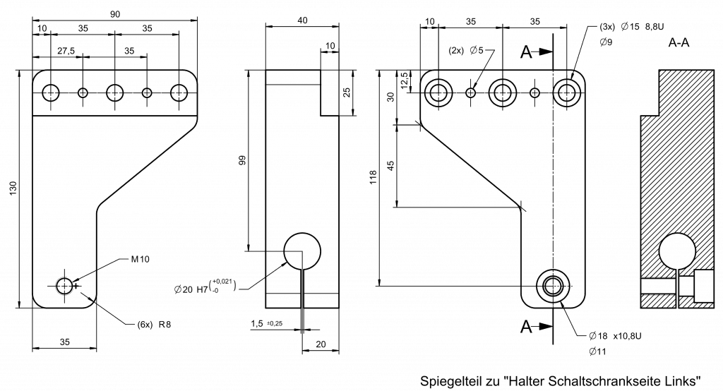
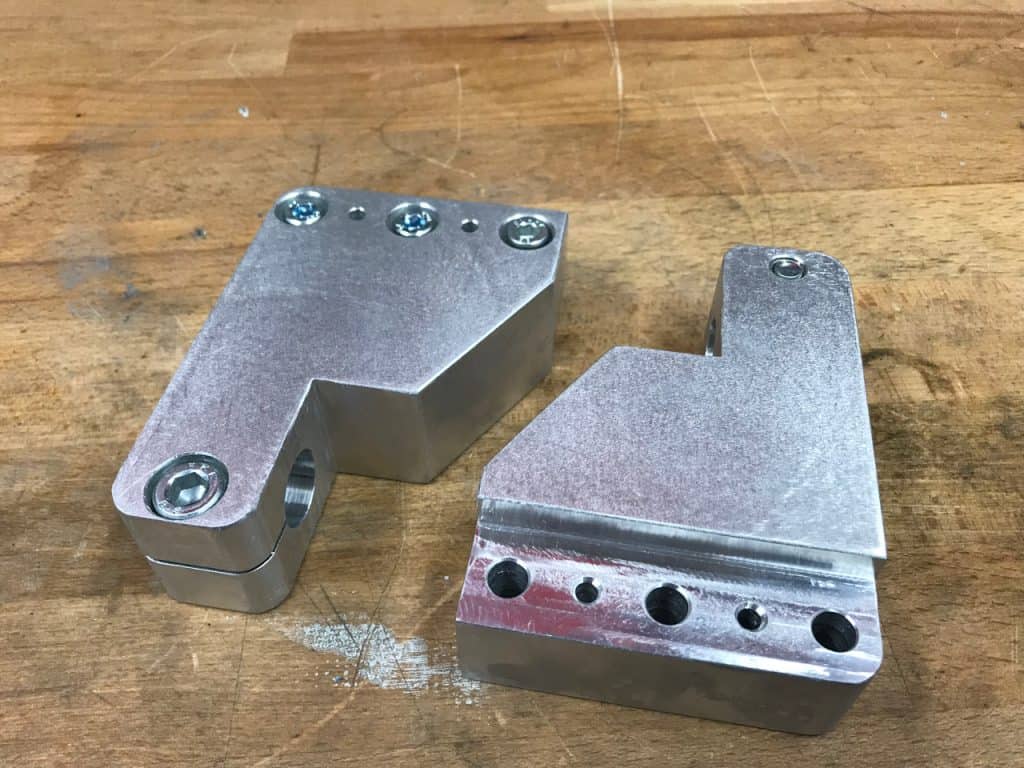
The part…
… was of course created in CAD by Fabian and will be used to hold the ball screws on the front side of the machine. Because we run one ball screw on each side of the machine this parts will need to be manufactured twice (mirrored).
Steps of machining
- 3 x 9 mm thru holes with a sink
- 3 x 5 mm thru holes
- 1 x 8,5 mm thru hole with sink and M10 thread
- One fit 20 mm H7
- One saw cut to clamp the ball screw
- One stance to index the holders
- Radius for most edges
Doesn’t look much for a professional but quite an adventure for me. After all, all parts of the assembly need to exactly fit together.
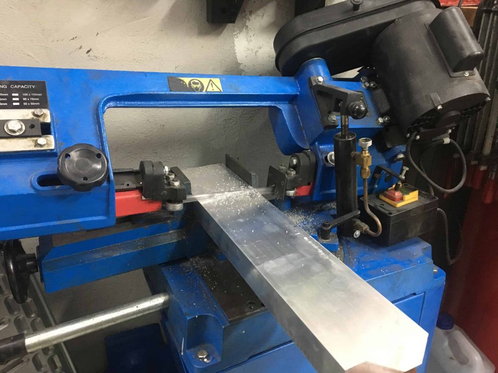
Machining
As with most of our work pieces we start at the band saw. I was lucky and the machine was behaving – some time ago we decided to permanently removed the rear blade cover because the saw developed a nasty habit of spitting out the saw blade. Probably this is caused by some clocked up bearings… We will need to perform some maintenance soon!
Raw stock
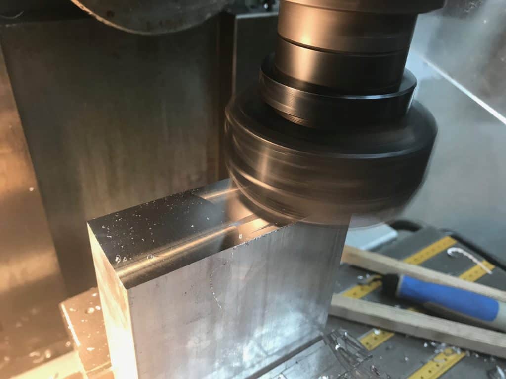
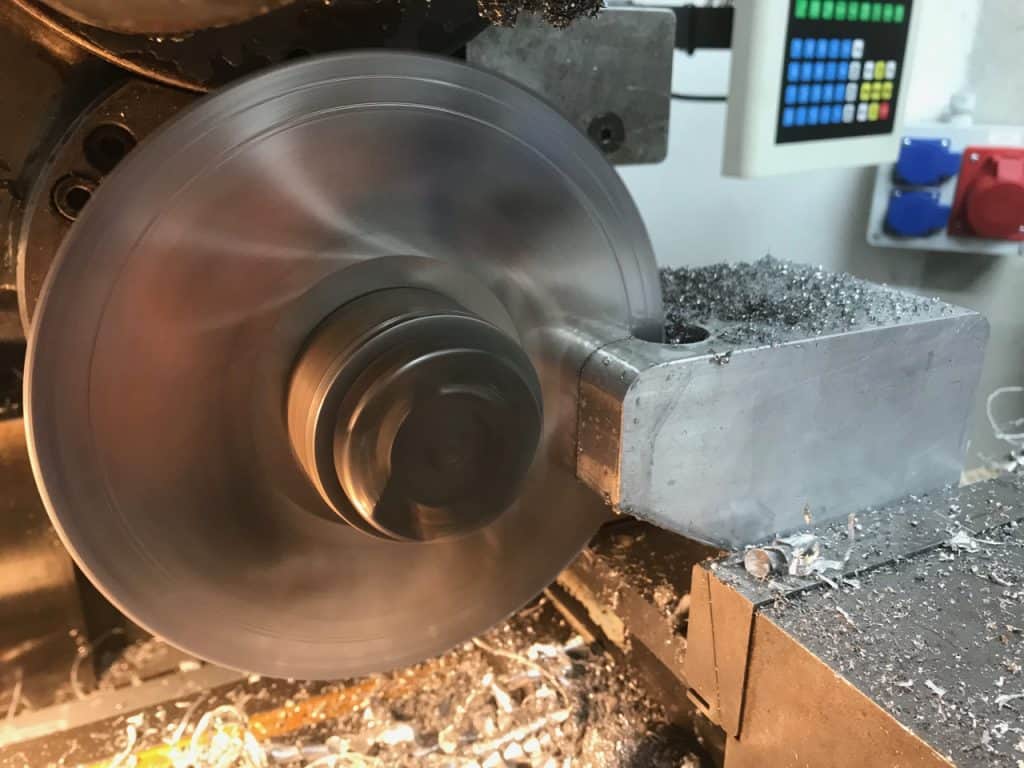
Next step is truing up the sides of the stock and bringing it down to final dimensions with my favourite tool, the facing head.
To cut down milling time the overall gemoetry was roughed out with the band saw first. Sawing is the most economic way to remove large chunks of stock, especially if the saw is semi-automatic.
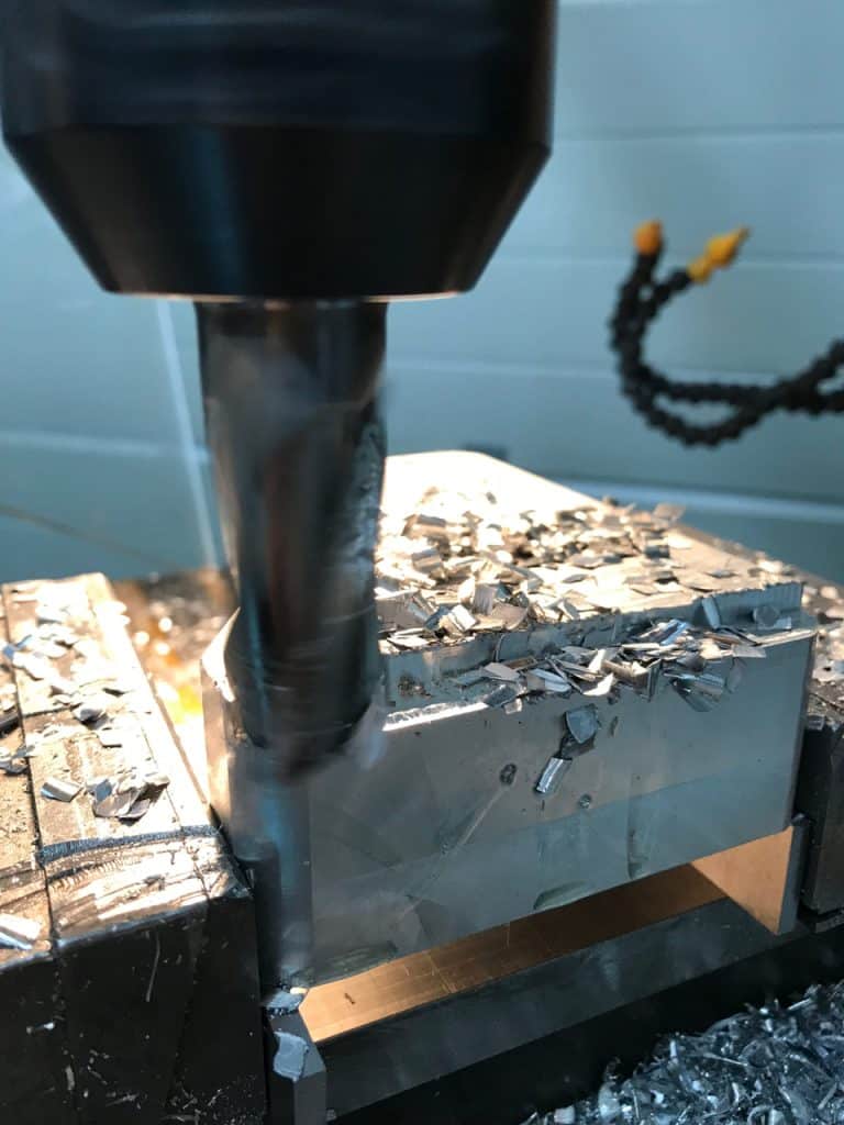
The rest of the machining is done with a 20 mm flat end mill.
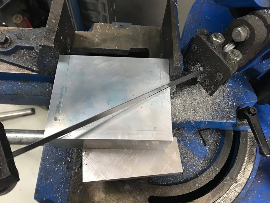
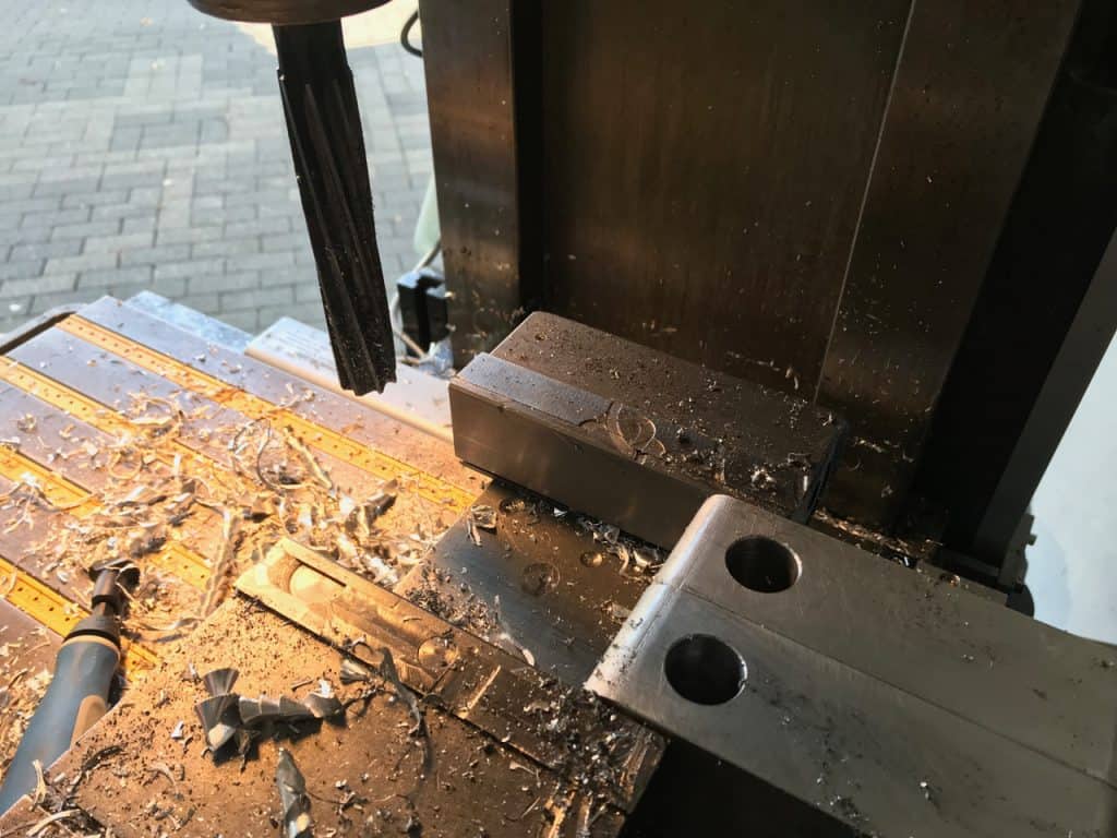
Slot cutting
Not sure if slot cutting is the correct term but I guess you will get the point. In order to clamp down the ball screw the 20 mm H7 fit had to be relieved.
Concentration! Last time I had (tried) to use a saw blade on the mill I manage to break it. Thanks to the engineering data reference book everything went well this time.
Reaming
The 20 mm fit with tolerance H7 first needed an appropriate pilot hole. The engineering data reference book demanded 0,3 to 0,4 mm undersize but the only drill sizes we have in the shop are 18 mm (too small) and 20 mm (too big). A few minutes at the bench grinder later and the 20 mm cheap “chinesium” spiral flute drill shrunk down to 19,06 mm.
Quick check before I continue with the remaining operations. The fit is perfect and the ball screw will be fixed perfectly.
The radii were machined using a quadrant cutter. This “ancient” tool comes from the pre-CNC time and still gives pretty good results.
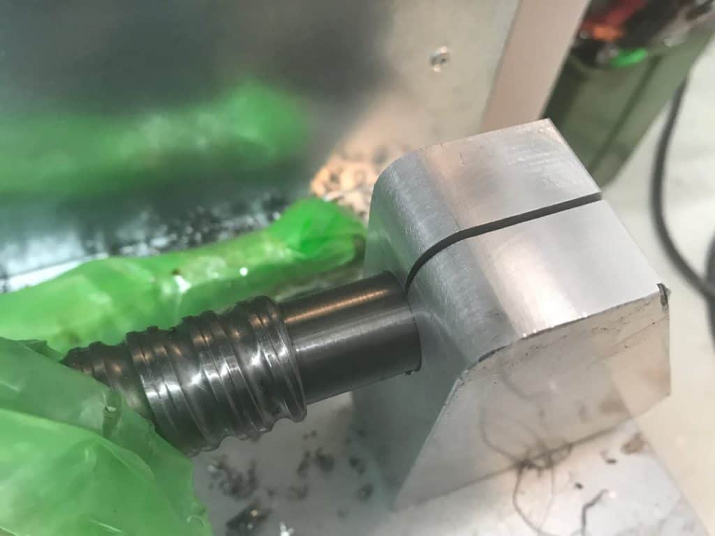
The result
Done! If you compare the part to the CAD model you will find that I rationalized some minor details of the part in order to speed up machining.
The surface was later on polished with an orbital surface grinder and 320 gauge sand paper.
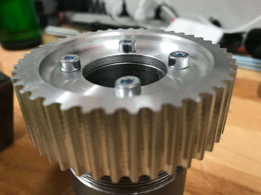
This left me with only a few last finishing touches on the parts Fabian hat procued on the lathe earlier… Drilling a few holes and cutting threads.
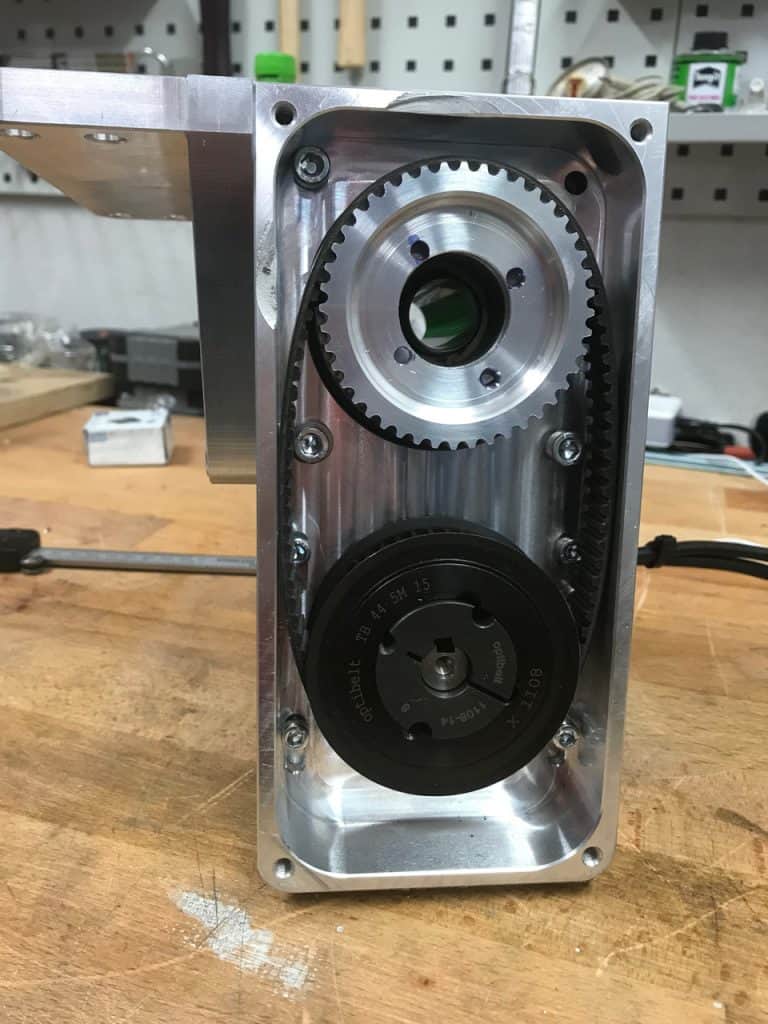
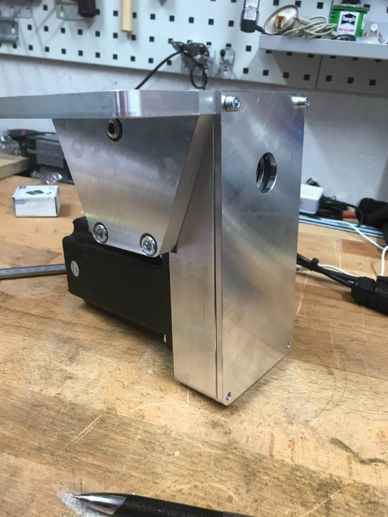
Next step
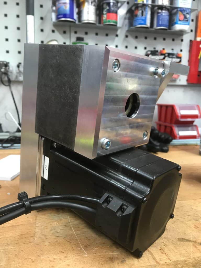
All parts are ready for assembly. Here is a first “loose-fit” test.
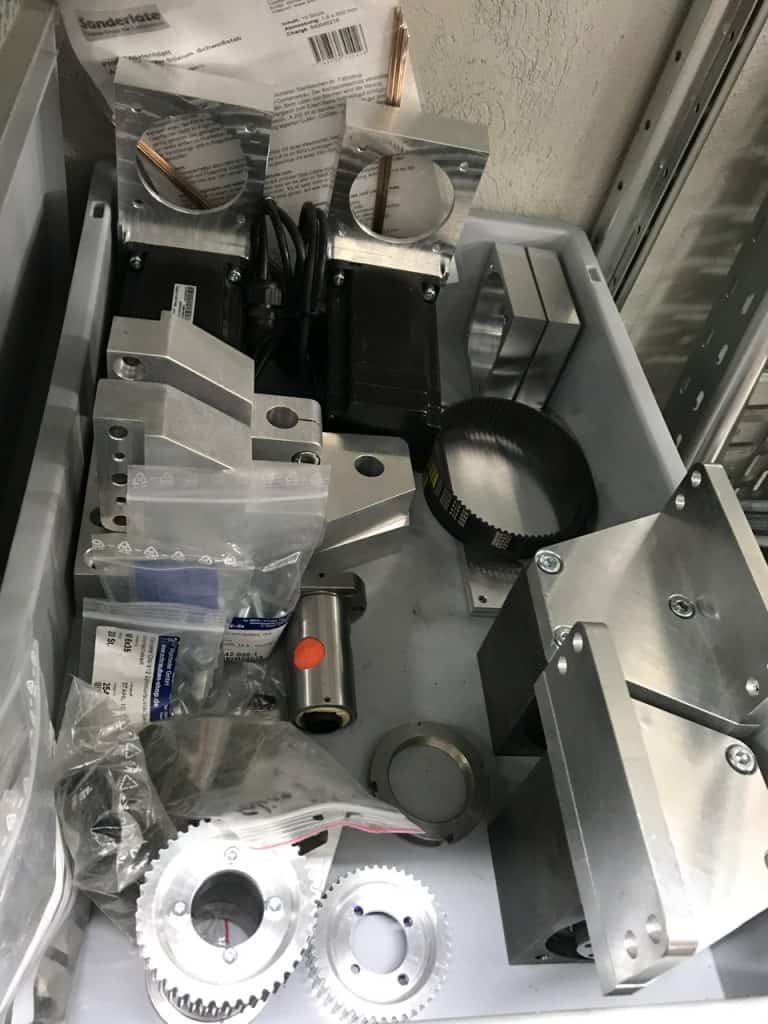
Some time ago we had started to use dedicated boxes, so called Euroboxes, per each project we start. The box format is standardized and allows to stack equal and half sized boxed above each other for better space management.


Hi Leute, mega geil wieder einmal. Dazu fällt mir aber gerade kurz ein, hat mein Chef im Sondermaschinenbau mal gesagt, Passungen werden nicht geschlitzt ^^
Hallo Roman,
Danke!
Zum Schlitzen: ist ja auch eine Klemmung (Festseite) und keine Passung 😉
Wir haben die Klemmung gerieben weil der selbst runter geschliffene Spiralbohrer keine so guten Oberflächen hinterlässt.
Cheers,
André